TM 55-1520-240-23-4
5-81.1
REPLACE SHOCK ABSORBER BRACKET BUSHINGS
(Continued)
5-81.1
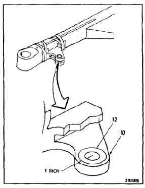
8.
Remove finish from plate (10) for 1 inch around
bushing bore (12). Use cloth (E120) damp with
acetone (E20). Wear gloves (E184.1).
9.
Inspect lower plate (10) in the area of finish
removal for condition as follows:
a.
If any damage in that area extends more than
0.030 inch from bushing hole (12), or hole is
elongated, reject the rotor blade.
b.
Measure bore (12) in two places; one parallel
to blade and one at right angle to blade. If the
bore is out of round by more than 0.002 inch
or exceeds the dimension for any bushing
listed in Table 1 below, it must be reamed to
the next largest size shown in Table 1 below.
c.
If bore (12) matches any size shown in Table
1, proceed to step 11. Install the proper
bushing.
TABLE 1
BUSHING
BORE
UPPER
LOWER
DIAMETER (INCHES)
REAMER
114R1774-4
114R1774-2
1.375 (+0.002-0.00)
-----
114R1774-6
114R1774-5
1.385 (+0.002-0.00)
1X
114R1774-8
114R1774-7
1.395 (+0.002-0.00)
2X
114R1774-10
114R1774-9
1.405 (+0.002-0.00)
3X
114R1774-12
114R1774-11
1.415 (+0.002-0.00)
4X
114R1774-14
114R1774-13
1.425 (+0.002-0.00)
5X
114R1774-16
114R1774-15
1.435 (+0.002-0.00)
6X
5-461


