TM 55-1520-240-23-3
4-118
ADJUST ENGINE DROOP ELIMINATOR VARIABLE RESISTORS
(Continued)
4-118
31.
If the No. 1 engine had a higher torque reading,
subtract the number recorded in step 29 from the
result found in step 30. If the No. 1 engine had a
lower torque reading, add the result found in step
29 to the result found in step 30.
32.
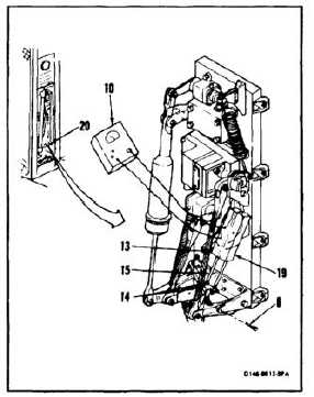
Loosen four nuts (14) on resistor shaft (15).
33.
Adjust resistor shaft (15) until multimeter (10)
reads amount of ohms equal to number recorded
in step 31.
34.
Tighten four nuts (14). Torque four nuts to 25
inch-pounds.
35.
If multimeter (10) reads amount recorded in step
33, go to step 37. If not, repeat steps 32 thru 36.
36.
Disconnect multimeter (10) from No. 1 resistor
(13).
37.
Repeat steps 30 thru 36 on No. 2 resister (19).
38.
Close No. 1 EMERG ENG TRIM circuit breaker
(1) on No. 1 power distribution panel (step 1).
39.
Close No. 2 EMERG ENG TRIM circuit breaker
(3) on No. 2 power distribution panel (step 2).
40.
Close DC TRIM circuit breaker (6) on No. 1
power distribution panel (step 4).
41.
Close DC TRIM circuit breaker (7) on No. 2
power distribution panel (step 5).
42.
Have pilot move thrust control through entire
range. There shall be no interference in resistor
installation (20) movement or thrust control
movement.
43.
Have pilot perform Droop Eliminator Flight Check
(TM 55-1520-240-MTF). If difference between
engine torque readings is 6 percent or more,
repeat steps 29 thru 43. If not, go to Follow-On
Maintenance.
FOLLOW-ON MAINTENANCE:
Adjust Engine Condition Control Resistor (Task
4-129).
Electrical power off.
Disconnect battery (Task 1-39).
Hydraulic power off.
Install controls closet panel (Task 2-2).
Install controls closet acoustic blanket (Task 2-108).
END OF TASK
4-418


