TM 55-1520-240-23-3
4-118
ADJUST ENGINE DROOP ELIMINATOR VARIABLE RESISTORS
(Continued)
4-118
RIG VARIABLE RESISTORS (OPTIONAL METHOD)
12.1.
Install rig pin (T133) in thrust control idler (step
6).
12.2
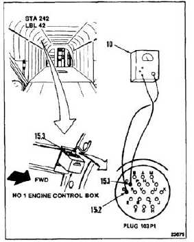
Connect multimeter (10) to pins C (15.1) and D
(15.2) on plug 103P1 (15.3) of the No. 1 engine
control box.
12.3.
Check multimeter (10). If multimeter reads 92 to
96 ohms, go to step 13. If not, go to step 12.4.
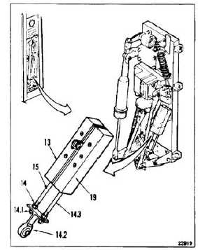
12.4.
Loosen one nut (14) above and one nut
(14.1) below the link assembly on the No. 1
potentiometer shaft (15).
12.5.
Adjust shaft until multimeter reads 92 to 96
ohms. If multimeter reads 92 to 96 ohms, go to
step 12.7. If not, go to step 12.6.
12.6.
Check nuts for thread protrusion. If all threads
of nuts are not engaged, replace engine droop
eliminator potentiometers (13 and 19) (Tasks
4-119 and 4-122).
12.7.
Make sure link (14.2) is parallel to resistor shafts
(15 and 14.3).
12.8.
Tighten one nut (14) above and one nut (14.1)
below the link assembly. Torque nuts to 25
inch-pounds. Apply Loctite to one nut (14).
12.9.
Disconnect multimeter from pins C and D. Go
to step 13.
12.10. Repeat steps 12.1 thru 12.9 for the No. 2 engine
control box. The No. 2 control box is located in
the right electrical equipment compartment then
go to step 13.
4-414