TM 55-1520-240-23-3
4-118
ADJUST ENGINE DROOP ELIMINATOR VARIABLE RESISTORS
(Continued)
4-118
RIG VARIABLE RESISTORS
NOTE
Adjustments for the No. 1 and the No.
2 resistors are the same. The No. 1
resistor is described.
Steps 12.1 thru 12.10 describes
the preferred method of rigging the
variable resistor because it checks
the active portion of the circuit and
the wiring from the resistor to the
control box. This has been added as
an option to steps 6 thru 12 which
checks only the inactive portion of the
variable resistor.
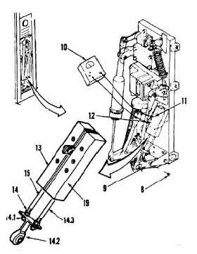
6.
Install rig pin (T133) (8) in thrust control idler (9).
7.
Connect multimeter (10) to terminals 1 (11) and
2 (12) on No. 1 potentiometer (13).
8.
Check multimeter (10). If multimeter reads 31 to
35 ohms, go to step 13. If not, go to step 9.
9.
Loosen one nut (14) above and one nut (14.1)
below the link assembly on No. 1 potentiometer
shaft (15).
10.
Adjust shaft until multimeter reads 31 to 35
ohms. If multimeter reads 31 to 35 ohms, go to
step 10.2. If not, go to step 10.1.
10.1.
Check nuts for thread protrusion. If all threads
of nuts are not engaged, replace engine droop
eliminator potentiometer (13 and 19) (Task 4-119
and 4-122).
10.2.
Make sure link assembly (14.2) is parallel to
resistor shafts (15 and 14.3).
10.3.
Tighten one nut (14) above and one nut (14.1)
below the link assembly (14.2). Apply Loctite to
one nut (14). Torque nuts to 25 inch-pounds.
11.
Disconnect multimeter (10) from terminals 1 (11)
and 2 (12). Go to step 13.
12.
Repeat steps 6 thru 11 for the No. 2
potentiometer (19).
4-413