TM 55-1520-240-23-3
4-118
ADJUST ENGINE DROOP ELIMINATOR VARIABLE RESISTORS
(Continued)
4-118
27.
Have pilot move thrust control through entire
range. There shall be no interference in resistor
installation (20) movement or thrust control
movement.
28.
Have pilot perform Droop Eliminator Flight Check
(TM 55-1 520-240-MTF). Maximum steady state
change in rotor rpm shall be 0 to -1 percent.
If rotor RPM is out of limits, repeat steps 18
thru 28. Maximum torque split between No. 1
and No. 2 engines shall not exceed 6 percent.
If torque split is out of limits, go to step 29. If
rpm and torque are in limits, go to Follow-On
Maintenance.
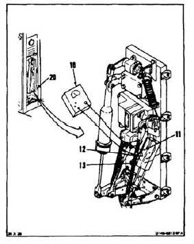
ADJUST RESISTORS FOR EXCESSIVE ENGINE
TORQUE SPLIT
29.
Record difference between engine torques
percentages and multiply by 0.6. Record number.
30.
Connect multimeter (10), set to RX1, to terminals
1 (11) and 2 (12) on No. 1 resister (13). Record
reading.
4-417