TM 55-1520-240-23-3
4-119
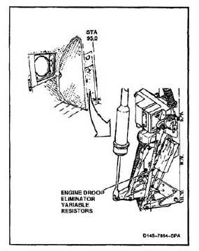
REMOVE ENGINE DROOP ELIMINATOR VARIABLE RESISTORS
4-119
INITIAL SETUP
Applicable Configurations:
Without 74
Tools:
Electrical Repairer’s Tool Kit, NSN 5180-00-323-4915
Materials:
Tape (E385)
Paper Tags (E264)
Personnel Required:
Aircraft Electrician
Equipment Condition:
Battery Disconnected (Task 1-39)
Electrical Power Off
Controls Closet Acoustic Blanket Removed (Task
2-101)
Controls Closet Panel Removed (Task 2-2)
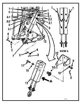
1.
Tag eight wires (1). Use paper tags (E264).
2.
Disconnect eight wires (1) by removing eight
screws (2). Remove eight washers (2.1) and
eight lockwashers (2.2), if installed. Remove
twine from resistors, if installed.
3.
Remove cotter pin (3), nut (4), two washers (5),
and bolt (6) from idler (7).
4.
Remove cotter pin (8), nut (9), two washers
(10), bushing (10.1), and bolt (11) from support
bracket (12).
5.
Remove resistors (13).
FOLLOW-ON MAINTENANCE:
None
END OF TASK
4-419