TM 55-1520-240-23-9
11-82
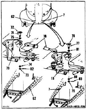
INSTALL COPILOT’S COCKPIT CONTROL ASSEMBLY
(Continued)
11-82
INSTALL PITCH CONNECTING LINK
42.
Working through right access (62), position
bellcrank (70) to align bolt (71) and hole (72).
43.
Remove nut (73), two washers (74 and 75) and
bolt (71) from bellcrank (70).
44.
Position pitch connecting link (76) in bellcrank
(70). Check that link is free of electrical wiring.
45.
Install bolt (71), two washers (75 and 74) and nut
(73) in bellcrank (70). Remove tag.
46.
Working through left access (7) position bellcrank
(18) to align bolt (77) and hole (78).
47.
Remove nut (79), two washers (80 and 81) and
bolt (77) from bellcrank (18).
48.
Position link (76) in bellcrank (18).
49.
Install bolt (77), two washers (81 and 80) and nut
(79) in bellcrank (18).
50.
Torque nuts (73 and 79) to 30 to 60 inch-pounds.
Install two cotter pins (82 and 83).
51.
Check bolts (71 and 77). Bolts shall not rotate
with torque less than 10 inch-pounds. There
shall be no axial looseness. If bolt rotates or is
loose, add washer under nut and repeat step 50.
11-433