TM 55-1520-240-23-9
11-82
INSTALL COPILOT’S COCKPIT CONTROL ASSEMBLY
(Continued)
11-82
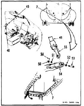
CONNECT THRUST CONTROL
28.
Have helper in cockpit, remove strap (48) from
thrust control (49). Set control fully down.
29.
Working through left access (7), remove nut (50),
two washers (51 and 52), and bolt (53) from
bellcrank (54).
30.
Position link (55) in bellcrank (54).
31.
Install bolt (53), two washers (52 and 51), and
nut (50) in bellcrank (54).
32.
Torque nut (50) to 30 to 45 inch-pounds
in accordance with standard torque limit
applications (Task 1-13, Note 5). Install cotter
pin (56).
33.
Check bolt (53). Bolt shall not rotate with torque
less than 10 inch-pounds. There shall be no
axial looseness. If bolt rotates or is loose, add
washer under nut and repeat step 32.
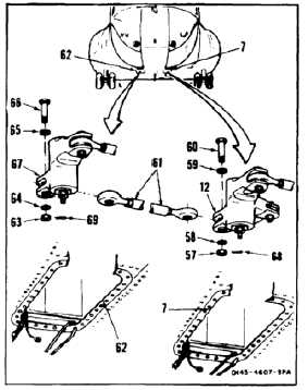
INSTALL THRUST CONNECTING LINK
34.
Working through left access (7), remove nut (57),
two washers (58 and 59), and bolt (60) from
bellcrank (12).
35.
Position thrust connecting link (61) in bellcrank
(12). Check that link is free of electrical wiring.
36.
Install bolt (60), two washers (59 and 58), and
nut (57) in bellcrank (12). Remove tag.
37.
Working through right access (62), remove nut
(63), two washers (64 and 65), and bolt (66) from
bellcrank (67).
38.
Position link (61) in bellcrank (67).
39.
Install bolt (66) two washers (65 and 64), and nut
(63) in bellcrank (67).
40.
Torque nuts (57 and 63) to 30 to 45 inch-pounds.
Install two cotter pins (68 and 69).
41.
Check bolts (60 and 66). Bolts shall not rotate
with torque less than 10 inch-pounds. There
shall be no axial looseness. If bolt rotates or is
loose, add washer under nut, and repeat step 40.
11-432