TM 55-1520-240-23-9
11-65
ASSEMBLE THRUST CONTROL (AVIM)
(Continued)
11-65
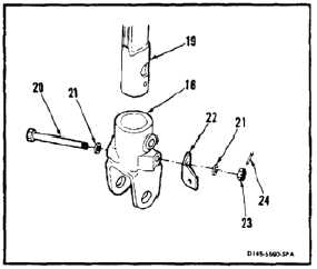
12.
Coat inside of large hole on top of end fitting (18)
with epoxy primer (E292). While primer is wet,
slide end fitting onto shaft (19). Align holes in
end fitting and shaft. Wear gloves (E184.1).
13.
Install bolt (20), two washers (21), clip (22) and
nut (23). Torque nut to 30 to 60 inch-pounds.
Install cotter pin (24).
14.
Check bolt (20). Bolt shall not rotate with torque
less than 10 inch-pounds. Bolt shall not have
axial looseness. If bolt rotates or is loose, add
washer (21) under nut (23). Torque and cotter
pin nut again.
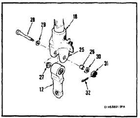
15.
Coat inside of holes in lugs (25) of end fitting (18)
with epoxy primer (E292). While primer is wet,
install bushing (26) and shoulder bushing (27).
Wear gloves (E184.1).
FLIGHT SAFETY PARTS
This is an installation critical flight
safety part. All aspects of its assembly
and installation must be ensured.
Ensure that both bearings and related
spacer are properly installed at upper
end of the link assembly.
Ensure single bearing is properly
installed and retained at the lower end
of the link assembly.
Ensure proper orientation of the link
assembly at installation.
At installation of this component,
ensure proper attaching hardware
(impedance type bolt, nut, and
washers) is installed including
verification of bolt head orientation,
torque, and installation of cotter pins.
Loose attachments within flight control
primary linkage will degrade aircraft
control. Missing components will
cause loss of control.
16.
Position link (12) in end fitting (18). Install bolt
(28), washers (29 and 30) and nut (31). Torque
nut to 30 to 60 inch-pounds. Install cotter pin
(32).
17.
Check bolt (28). Bolt shall not rotate with torque
less than 10 inch-pounds. Bolt shall not have
axial looseness. If bolt rotates or is loose, add
washer (30) under nut (31). Torque and cotter
pin nut again.
11-294