TM 55-1520-240-23-3
4-75
INSTALL ENGINE AIR INLET FAIRING
(Continued)
4-75
NOTE
Engine access cover is not shown for
clarity.
3.
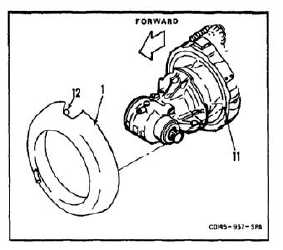
Position fairing (1) on engine (11) so locating pin
(12) aligns with engine.
3.1.
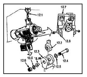
Slowly lower hoist (12.1) until lower end of aft
engine mount link (12.2) aligns with mount (12.3).
Install bolt (12.4), washers (12.5), and nut (12.6).
Torque nut (12.6) to 350 to 400 inch-pounds to
seat bushing (12.18). Loosen nut and retorque
nut to 20 inch-pounds above run-on torque
value, but in no case should the torque be less
that 70 inch-pounds.
4.
Continue to lower hoist (12.1) slowly until forward
adapters (12.7) rest on caps (12.8).
5.
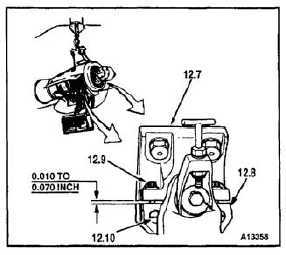
Check that friction torque of bolts (12.9) in barrel
nuts (12.10) is not less than 7 inch-pounds.
5.1.
Push four bolts (12.9) up and over adapter (12.7).
5.2.
Torque bolts (12.9) to 105 inch-pounds. Check
that gap between adapters (12.7) and caps
(12.8) is 0.010 to 0.070 inch.
5.3.
If gap measurement exceeds 0.010 to 0.070
inch, repair mount (Task 4-32), and repeat step
5.2.
5.4.
Check bolts (12.9). Bolt threads shall protrude
a minimum of two threads through barrel nuts
(12.10), but shall not bottom out. Add washers
under bolthead if bolt is bottoming out. Lockwire
bolts. Use lockwire (E231).
INSPECT
4-321


