TM 55-1520-240-23-9
11-52
ADJUST FIRST AND SECOND STAGE BELLCRANK CUMULATIVE STOPS
(Continued)
11-52
Do not stand, kick, or induce lateral
loads to the thrust idler. A cracked
arm will cause in-flight failure resulting
in disconnecting the thrust cockpit
driver actuator (CCDA) and the
droop eliminator potentiometers
(Without 74 ) or thrust control position
transducer (With 74 ).
1.
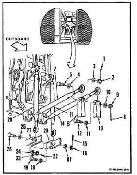
Working in passageway, remove cotter pin (1),
nut (2), two washers (3 and 4), and bolt (5) from
bellcrank (6). Disconnect link (7) from bellcrank.
Tie link away from bellcrank. Use twine (E433).
2.
Remove cotter pin (8), nut (9), two washers
(10 and 11), and bolt (12) from bellcrank (13).
Disconnect link (14) from bellcrank. Tie link away
from bellcrank. Use twine (E433).
3.
Remove cotter pin (15), nut (16), two washers
(17 and 18), and bolt (19) from bellcrank (20).
Disconnect link (21) from bellcrank. Tie away
from bellcrank. Use twine (E433).
4.
Remove cotter pin (22), nut (23), two washers
(24 and 25), and bolt (26) from bellcrank (27).
Disconnect link (28) from bellcrank. Tie away
from bellcrank. Use twine (E433).
5.
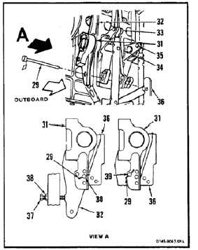
Working from passageway, install first stage rig
pin (T44) (29) through hole (30) in fitting (31), four
bellcranks (32, 33, 34, and 35) and in fitting (36).
6.
Adjust down thrust stop bolt (37). Loosen nut
(38). Turn bolt until bolt just touches bellcrank
(32). Tighten nut (38).
7.
Remove pin (29) from fitting (36), bellcranks (32,
33, 34, and 35), and fitting (31).
8.
Install pin (29) through hole (39) of fitting (31)
and four bellcranks (32, 33, 34, and 35), and in
fitting (36).
NOTE
Bellcranks (32 and 33) have oversize
holes.
11-223