TM 55-1520-240-23-7
9-101.2
INSTALL OVERHEAD PANEL LIGHTING POTENTIOMETER, LIGHTING CONTROL
TRANSFORMERS, OR ROTARY SWITCH
(Continued)
9-101.2
29.
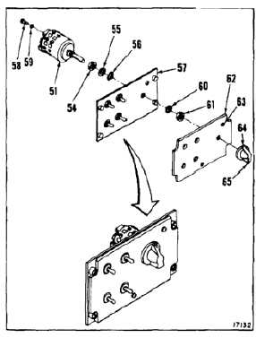
Install nut (54), washer (55), and lockring (56) on
shaft of rotary switch (51).
30.
Position rotary switch (51) in panel (57) with shaft
flat opposite terminal 11. Engage bent tab of
lockring (56) with locking hole in mounting panel.
31.
Install two limit screws (58) and washers (59)
into tapped holes on rear cover plate of switch
between terminals 26 and 27 and between
terminals 28 and 21.
32.
Install washer (60) and nut (61) on shaft of rotary
switch (51) and panel (57).
33.
Install lighting panel (62) on panel (57) with two
screws (63). Tighten screws.
34.
Install knob (64) on rotary switch (51). Tighten
screw (65).
35.
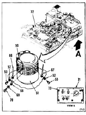
Remove tape and install one wire (66) with
washer (52), screw (53), along with one end of
the installed resistor (50) on terminal 26 of rotary
switch (51).
36.
Remove tape and install one wire (67) with
washer (52) and screw (53) on terminal 21 of
rotary switch (51).
37.
Remove tape and install six wires (68) with
washers (69) and screws (70) on first wafer of
rotary switch (51). Remove tags.
INSPECT
38.
Install panel (71) in overhead panel (72). Tighten
four screws (73).
FOLLOW-ON MAINTENANCE:
Perform operational check (TM 55-1520-240-T).
END OF TASK
9-411


