TM 55-1520-240-23-6
7-96
INSTALL EXTENSIBLE LINK SERVO VALVE (AVIM)
(Continued)
7-96
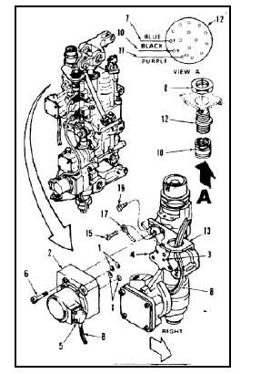
NOTE
Servo valve (2) has an aligning pin on
its base. Be careful that pin seats in
its mating hole (3) in manifold (4).
2.
Position servo valve (2) on manifold (4) with
adapter (5) to the right. Install four screws (6).
Torque screws to 30 inch-pounds and lockwire
(E230).
3.
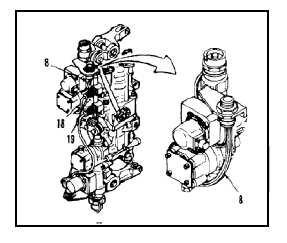
Thread cable (8) through backshell (9) and
connect blue wire (7) of cable (8) to pin
No. 8 of connector/receptacle (12). Use
insertion/extraction tool. Remove tag.
4.
Connect black wire (10) to pin No. 9. Use
insertion/extraction tool. Remove tag.
5.
Connect purple wire (11) to pin No. 10. Use
insertion/extraction tool.
6.
Position connector/receptacle (12) in bracket
(13) from underside. Install locknut (14) on
connector/receptacle. Use lockwire (E227).
7.
Install backshell (9) on connector/receptacle (12).
8.
Install bracket (13) on manifold (4). Use screws
(15 and 16), ground connector by installing screw
with beveled head (15) through terminal lug (17).
9.
Torque screws (15 and 16) to 30 inch-pounds
and lockwire (E230).
10.
Tie cable (8) to cables (18 and 19). Use twine
(E433).
INSPECT
FOLLOW-ON MAINTENANCE:
Test extensible link (Task 7-97).
END OF TASK
7-376