TM 55-1520-240-23-6
7-269.1
TEST 145HS775 RAMP CONTROL VALVE (AVIM)
(Continued)
7-269.1
39.
Configure ramp control valve as described in
step 35 but with ramp control valve handle (16)
set in position 2 (stop).
40.
Set power supply to 18 vdc.
41.
On ramp control valve test set (21) (APP E-317),
set SOLENOID VALVE SELECT switch (23) to
BOTH, and PWR switch (22) to ON. Both UP and
DN SOL lights (25 and 26) shall be on.
42.
Operate ramp control valve through five
electrical cycles using ramp control valve test
set (21). Each cycle shall consist of steps a
through d. Actuation shall be without hesitation
or binding.
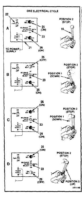
a.
Set SOLENOID VALVE SELECT switch (23)
to BOTH (see A). Both UP and DN SOL lights
(25 and 26) of test set (21) (APP E-317) shall
come on and ramp control valve handle (16)
shall remain in position 2 (stop).
b.
Set SOLENOID VALVE SELECT switch (23)
to DN (see B). DN SOL light (26) shall remain
on, UP SOL light (25) shall extinguish, and
ramp control valve handle (16) shall move
to position 1 (down).
c.
Set SOLENOID VALVE SELECT switch (23)
to BOTH (see C). Both UP and DN SOL lights
(25 and 26) shall come on and ramp control
valve handle (16) shall move from position 1
to position 2 (stop).
d.
Set SOLENOID VALVE SELECT switch (23)
to UP (see D). UP SOL light (25) shall come
on, DN SOL light (26) shall extinguish, and
ramp control valve handle (16) shall move to
position 3 (up). Return to step a for beginning
of next cycle.
43.
Repeat step 42 while increasing voltage to 30
vdc. Valve shall operate without binding.
44.
Remove hydraulic pressure from ramp control
valve (2), and set ramp control valve test set
PWR switch (22) to OFF.
7-1004