TM 55-1520-240-23-6
7-269.1
TEST 145HS775 RAMP CONTROL VALVE (AVIM)
(Continued)
7-269.1
NOTE
During all tests, external static seal
leakage shall not exceed a slight
wetting insufficient to form a drop.
Leakage from external dynamic piston
seals shall not exceed 1 drop per 25
cycles of motion.
Unless specified, the following tests
shall be performed with test plug
(T179) installed in place of thermal
relief valve.
11.
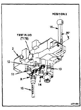
Install pressure caps (11, 12, 13, and 14) on
ports C3, C2, C1, and P of ramp control valve (2).
12.
Connect hydraulic pressure line (15) to return
port R of ramp control valve (2).
13.
Set handle (16) to position 2 (stop) with both
solenoids de-energized, and apply 2515 psig to
pressure line (15) in return port R.
14.
Hold pressure on return port R for 2 minutes
minimum. Check that external leakage is minimal
with no permanent deformation of parts.
15.
Remove pressure and disconnect pressure line
(15) from return port R.
16.
Remove caps (12, 13, and 14) from cylinder
ports C2, and C1, and pressure port P.
17.
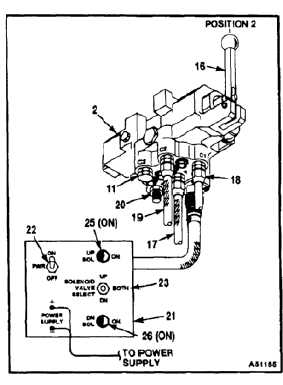
Connect pressure lines (17, 18, and 19) to ports
P, C1, and C2. Leave return port R (20) open to
atmosphere and cap (11) on cylinder port C3.
18.
Connect ramp control valve test set (E317) (21)
to ramp control valve (2) and power suppy. Set
power supply to provide 30 vdc.
19.
Set PWR switch (22) to ON, ramp SOLENOID
VALVE SELECT switch (23) to BOTH, and ramp
control valve handle (16) to position 2 (stop).
Both UP and DN SOLENOID lights (25 and 26)
shall come on, indicating power is applied to
both solenoids.
20.
Apply 5025 psig simultaneously to lines (17, 18,
and 19) in ports P, C1, and C2. Ramp control
valve handle (16) shall remain in position 2 (stop).
21.
Hold pressure for 2 minutes. Make sure
external leakage is minimal with no permanent
deformation of parts.
22.
Remove pressure and remove pressure lines (18
and 19) from ports C1 and C2.
7-1001


