TM 55-1520-240-23-6
7-269.1
TEST 145HS775 RAMP CONTROL VALVE (AVIM)
(Continued)
7-269.1
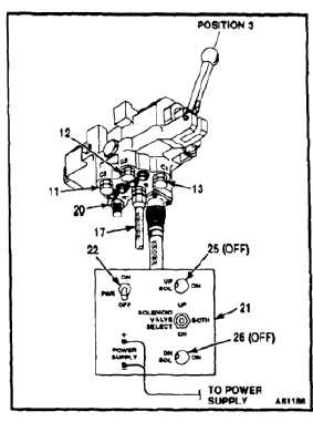
23.
Set ramp control valve test set (21) (APP E-317)
PWR switch (22) to OFF. UP and DN SOL lights
(25 and 26) on test set shall go off.
24.
Install pressure caps (12 and 13) on ports C2
and C1, and check secuirty of pressure cap (11)
on port C3. Return port R (20) shall remain open.
25.
Move ramp control valve handle (16) to position
3 (up).
26.
Apply 5025 psig to pressure line (17) in pressure
port P.
27.
Hold pressure for 2 minutes. Make sure external
leakage is minimal and that no permanent
deformation of parts occurs. Release pressure.
NOTE
Seals must be properly installed on
thermal relief valve as described in
Task 7-268.1, or ramp control valve
will fail to operate properly.
28.
Remove test plug (6) (T179).
29.
Install new packings (3 and 4) and piston cap
seal (5) on thermal relief valve (1) (Task 7-268.1).
30.
Install thermal relief valve (1) in ramp control
valve (2) as described in Task 7-268.1.
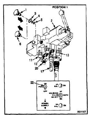
31.
Move ramp control valve handle (16) to position
1 (down).
32.
Check security of caps (11, 12, and 13) on ports
C3, C2, and C1. Return port R (20) shall remain
open, and test set PWR switch (22) set to OFF.
33.
Apply 5025 psig to pressure line (17) in pressure
port P.
34.
Hold pressure for 2 minutes. Make sure external
leakage is minimal and that no permanent
deformation of parts occurs. Release pressure.
7-1002