TM 55-1520-240-23-6
7-269.1
TEST 145HS775 RAMP CONTROL VALVE (AVIM)
(Continued)
7-269.1
NOTE
Same part number packings and
piston seal are used on thermal relief
valve and test plug. Refer to Task
7-268.1 for installation of seals.
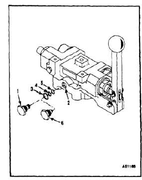
1.
Remove thermal relief valve (1) from ramp
control valve (2).
NOTE
All tests assume that the ramp
control valve is preconfigured with the
appropriate unions in ports C1, C2,
C3, F, and R. Pressure caps are to be
installed on those unions.
2.
Install new packings (3 and 4) and piston seal (5)
on test plug (6) (T179).
3.
Install test plug (6) (T179) in thermal relief valve
port of ramp control valve (2). Torque plug to 133
to 147 inch-pounds.
NOTE
Unions are shown in test block to
clarify orientation of ports with thermal
relief valve. Test block ports are
manufactured to MS33649-04.
The thermal relief valve is not
repairable and shall be replaced if it
fails the following tests.
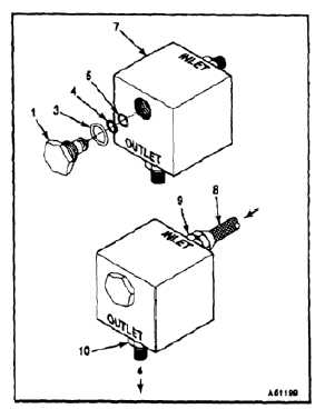
4.
Install new packings (3 and 4) and piston seal (5)
on thermal relief valve (1).
5.
Install thermal relief valve (1) in port of test fixture
(7) (T178). Torque thermal relief valve to 133
to 147 inch-pounds.
6.
Connect test stand pressure line (8) to inlet port
(9) of test fixture (7) (T178).
7.
Increase pressure to 3000 psig. Leakage from
test fixture outlet port (10), shall not exceed 1
drop per minute (dpm).
8.
Continue to increase pressure until flow from
outlet port (10) is 5 cc per min. Inlet pressure
shall be between 3850 and 4350 psig.
9.
Decrease inlet pressure to 3000 psig, and
measure leakage from outlet port (10). Leakage
shall not exceed 1 drop per minute (dpm).
10.
If the thermal relief valve (1) passes these tests,
lubricate thermal relief valve with hydraulic fluid
(E199) and place in plastic bag (E78). Replace
thermal relief valve if it fails any of the above
tests.
7-1000