TM 55-1520-240-23-6
7-269.1
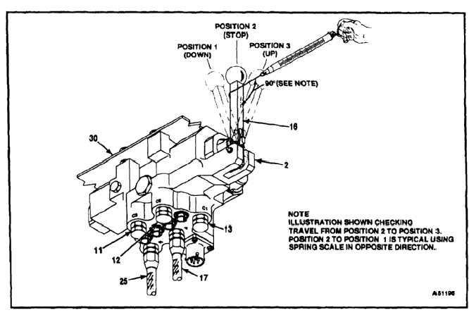
TEST 145HS775 RAMP CONTROL VALVE (AVIM)
(Continued)
7-269.1
46.
Configure and test ramp control valve to
determine manual operating forces, as follows:
a.
Remove all pressure and electrical power
from ramp control valve (2).
b.
Remove pressure line from port C2 and
install pressure cap (12). Caps (11 and 13)
shall remain on ports C3 and C1.
c.
Connect separate pressure lines (17 and 25)
to pressure port P, and return port R.
d.
Install ramp control valve in fixture (30).
e.
Apply 3000 psig to pressure line (17) in
pressure port P and 80 psig to pressure line
(25) in return port R.
f.
Place ramp control valve handle (16) in
position 2 (stop).
g.
Use a spring scale to apply a steadily
increasing force perpendicular to ramp
control valve handle (16) until handle moves
to position 3 (up). Force required to actuate
handle shall be 5 to 20 pounds without
apparent binding or malunction.
h.
Repeat previous step, moving handle (16)
from position 2 (stop) to position 1 (down).
FOLLOW-ON MAINTENANCE:
None
END OF TASK
7-1008