TM 55-1520-240-23-6
7-267.1
DISASSEMBLE AND INSPECT 145HS775 RAMP CONTROL VALVE
(Continued)
7-267.1
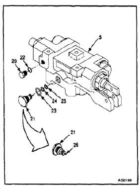
d.
Thread set screw into handle until it bottoms.
e.
Apply one drop of sealing compound
(E342.3) to exposed threads of set screw (9)
that will thread into knob (8).
f.
Screw knob (8) onto handle until it bottoms.
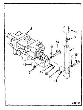
7.
Remove cotter pins (10 and 11) and washers (12
and 13) from pins (14 and 15).
8.
Remove pin (14) and washer (16) from handle
(1).
NOTE
To prevent detent ball (18) from
springing free, take care when
removing pin (16) from handle (1).
9.
Remove pin (15) and washer (17) and carefully
remove handle (1) from between clevis of valve
body (5). Grasp detent ball (18) if it exits valve
body.
10.
Remove bail (18) and spring (19) from valve
body (5).
11.
Remove lockwire from plug (20) and relief valve
assembly (21).
12.
Remove plug (20) and relief valve assembly (21)
from valve body (5).
13.
Remove packing (22) from plug (20).
14.
Remove packings (23 and 24) and piston (cap)
seal (25) from relief valve assembly (21).
15.
Inspect seats that receive packings (23 and 24)
and piston seal (25) on relief valve assembly (21).
The seats shall be free of nicks or scratches.
16.
Inspect plunger (26) on relief valve assembly
(21) for condition and freedom of movement.
7-975