TM 55-1520-240-23-6
7-267.1
DISASSEMBLE AND INSPECT 145HS775 RAMP CONTROL VALVE
(Continued)
7-267.1
NOTE
Due to potting requirements, it may be
necessary to replace connector and
both diodes if it becomes necessary to
remove wires from back of connector.
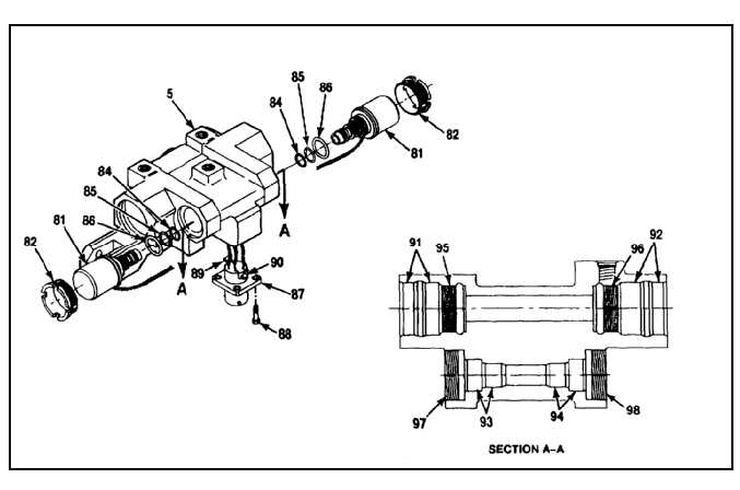
46.
Proceed as follows to remove solenoid valves
(81) and connector (87) from valve body (5).
a.
Remove lockwire from four screws (88) and
remove screws from connector and valve
body.
b.
Remove connector (87) from valve body (5).
It may be necessary to pry connector from
valve body due to use of potting compound to
secure and insulate wires and diodes behind
connector.
c.
Remove potting compound from around
wires, diodes (89 and 90), and back of
connector (87).
d.
Unsolder wires and diodes (89 and 90) from
back of connector (87). Make sure all potting
is removed from wires of solenoid valve (81)
being removed.
e.
Remove lockwire from locking ring (82) and
remove locking ring.
Do not pull hard on solenoid valve as
this could damage valve wiring.
f.
Remove solenoid valve(s) (81) from valve
body (5) and pull wires from body.
47.
Inspect seal bearing surfaces (91, 92, 93, and
94), and threaded areas (95, 96, 97, and 98)
inside valve body (5). Seal bearing surfaces
shall be as smooth as possible and free of
nicks or scratches. Threads shall be free of
contamination and not damaged in any way.
FOLLOW-ON MAINTENANCE:
None
END OF TASK
7-980