TM 55-1520-240-23-4
5-87.1
INSPECT SHOCK ABSORBER WITH TEFLON BEARINGS
(Continued)
5-87.1
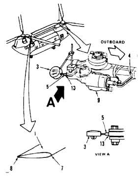
12.
Connect shock absorber (9) at bracket (4) (Task
5-93).
13.
Mount indicator (3) on inboard lug (10). Position
indicator plunger (5) against inboard end (13) of
absorber (9), at midstroke of plunger. Align with
absorber axis.
14.
Record indicator (3) reading.
15.
Have helper apply force to tip of blade (1) at
leading edge (7). Blade should just move.
Record indicator (3) reading C.
16.
Have helper apply force to tip of blade (1) at
trailing edge (8). Blade should just move. Record
indicator reading D.
17.
Subtract reading D of step 16 from reading C of
step 15. Result must not be more than 0.010
inch. If not more, go to step 23. If more, perform
steps 18 thru 22, then go to step 23.
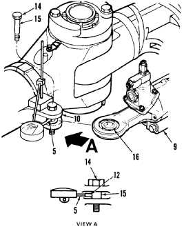
18.
Disconnect absorber (9) at unboard lug (10)
(Task 5-87).
19.
Check bolt (14) for wear. Bolt shank (15) shall be
smooth, with no radial wear marks.
20.
Install bolt (14) in lug (10). Position indicator
plunger (5) against bolt shank (15). Align with
bolt axis. Use plunger with flat end (12).
21.
Check bolt (14) movement. Attempt to move bolt
toward, then away from plunger (5). Movement
shall not be more than 0.0015 inch.
22.
If results from steps 19 and 21 are not cause
of excess movement, replace absorber inboard
bearing (16) (Task 5-89.2).
23.
Connect shock absorber (9) at inboard lug (10)
(Task 5-93).
FOLLOW-ON MAINTENANCE:
Remove tiedown lines from blades (Task 1-26).
Close work platforms (Task 2-2).
END OF TASK
5-527