TM 55-1520-240-23-4
5-87.1
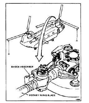
INSPECT SHOCK ABSORBER WITH TEFLON BEARINGS
5-87.1
INITIAL SETUP
Applicable Configurations:
Without 45
Tools:
Aircraft Mechanic’s Tool Kit, NSN 5180-00-323-4692
Rope Guidelines
Dial Indicator, 0 to 0.030 Inch, NSN 5210-00-277-8840
C-Clamp
Micrometer
Materials:
None
Personnel Required:
Medium Helicopter Repairer
Inspector
References:
Task 1-58
Task 5-87
Task 5-88
Task 5-89
Task 5-90
Task 5-93
Equipment Condition:
Battery Disconnected (Task 1-39)
Electrical Power Off
Hydraulic Power Off
Tiedown Lines Attached to Three Rotary-Wing Blades
(Task 1-26)
Work Platforms Open (Task 2-2)
Do not allow blade to swing. Blade
can cause injury or damage to
components.
NOTE
Positive retention bolts are installed
in shock absorber bearings. They
have a pawl which prevents nut or bolt
removal unless the pawl is depressed.
Procedure is same to inspect any
shock absorber. There are six shock
absorbers.
1.
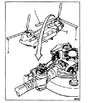
Position rotary-wing blade (1) over fuselage (2).
Have helper hold blade in position.
1.1.
Check for oil leakage. Static leakage at any
location shall not exceed a slight wetting.
Leakage shall be less than one drop. If more,
replace shock absorber (Tasks 5-87 and 5-93).
Perform operational leakage inspection (Task
1-58).
5-525