TM 55-1520-240-23-7
8-83
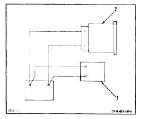
TEST HYDRAULIC PRESSURE INDICATOR
8-83
INITIAL SETUP
Applicable Configurations:
All
Tools:
Electrical Repairer’s Tool Kit, NSN 5180-00-323-4915
DC Power Supply, 0-5 Volt
Connector, MS3476W10-6S
Calibrated Voltmeter
Materials:
None
Personnel Required:
Aircraft Electrician
Inspector
Equipment Condition:
Off Helicopter Task
Test Setup
Be careful when handling indicator.
Rough handling will damage indicator.
1.
Turn on and adjust dc power supply (1) to 0 volts.
2.
Connect indicator (2) to test setup.
3.
Adjust power supply to settings listed. Indicator
readings shall be as follows:
NO BREAK - WORK HARDER
DC SOURCE
MIN
VOLTAGE
MAX
SCALE
READING
(PSI)
1.410
1.590
1000
2.410
2.590
2000
3.410
3.590
3000
4.410
4.590
4000
4.
Adjust power supply (1) to 0 volts and shut down.
5.
Disconnect indicator (2) from test setup.
FOLLOW-ON MAINTENANCE:
None
END OF TASK
8-271