TM 55-1520-240-23-9
11-17
REMOVE DAMAGED RIG PIN FROM THRUST CONTROL
(Continued)
11-17
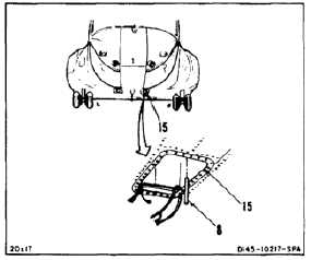
15.
Working through access (15), remove pin (8).
16.
Inspect thrust control assembly for damage (Task
11-18).
Bushings must be in bellcranks before
installing bolts; otherwise, damage to
components will result.
NOTE
Impedance bolts are installed in flight
control connections. These bolts are
self-retaining and require a special
nut and torque (Task 1-13).
17.
Working through access (15) position bellcrank
(24) in fitting (37) hole (39) aft and arm (40)
inboard.
18.
Install bolt (36), two washers (35 and 34), and nut
(33) in fitting (37). Do not torque nut at this time.
19.
Position link (31) in bellcrank (24). Install bolt
(30), two washers (29 and 28) and nut (27). Do
not torque nut at this time.
20.
Position link (25) in bellcrank (24). Install bolt
(23), two washers (22 and 21), and nut (20).
21.
Torque three nuts (20, 27, and 33) to 30 to 45
inch-pounds. Install three cotter pins (19, 26,
and 32).
22.
Check three bolts (23, 30, and 36). Bolts shall
not rotate with torque less than 10 inch-pounds.
There shall be no axial looseness. If bolt rotates
or is loose, add washer under nut and repeat
step 21.
INSPECT
11-72