TM 55-1520-240-23-9
11-94
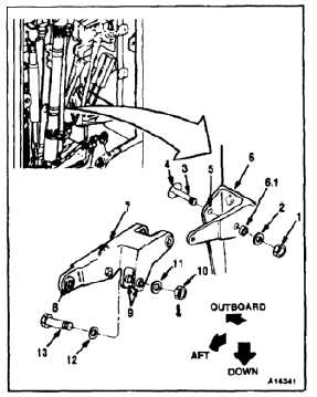
INSTALL YAW IDLER BELLCRANK
(Continued)
11-94
Bushings must be in bellcrank
and support before installing bolts;
otherwise, damage to components
will result.
NOTE
Impedance bolts are installed in flight
control connections. These bolts are
self-retaining and require a special
nut and torque (Task 1-13).
NOTE
If a crack in the connecting link,
bellcrank, or support is suspected
during disassembly, refer to TM
1-1520-253-23.
1.
Remove nut (1) and washer (2) from bolt (3).
Slide bolt outboard through hole (4) until flush
with lug (5) of support (6).
1.1.
Remove slipfit bushing (6.1) from support (6).
Clean bushing and bore with dry cleaning solvent
(E162) and cloth (E120). Wear gloves (E184.1)
and goggles.
1.2.
Coat bushing (6.1) with epoxy primer (E292).
Install bushing wet in support (6).
FLIGHT SAFETY PARTS
This is an installation critical flight
safety part. All aspects of its assembly
and installation must be ensured at
each joint connection and mounting to
the airframe.
Ensure that all bushings are
properly installed (including bushing
orientation) in each input and output
clevis and lug of the idler.
Ensure idler hub bearings are
serviceable and properly installed.
Ensure proper attaching hardware
associated with all components
mounted to this idler assembly
itself (impedance type bolt, nut,
and washers) is installed including
verification of bolt head orientation,
torque, and installation of cotter pins.
Loose attachments within flight control
primary linkage will degrade aircraft
control. Missing components will
cause loss of control.
2.
Position yaw idler bellcrank (7), lug (8) aft, and
two lugs (9) down in support (6). Install bolt (3),
washer (2), and nut (1) in support. Do not torque
nut at this time.
11-496