TM 55-1520-240-23-9
11-93
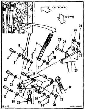
REMOVE YAW IDLER BELLCRANK
(Continued)
11-93
NOTE
If a crack in the connecting link,
bellcrank, or support is suspected
during removal, refer to TM
1-1520-253-23.
NOTE
Attaching bolts, washers, and nuts will
be temporarily installed after removing
links and bellcrank.
1.
Remove cotter pin (1), nut (2), two washers
(3), and bolt (4) from yaw idler bellcrank (5).
Disconnect spring assembly (6) from bellcrank.
Tie spring assembly away from bellcrank. Use
twine (E433).
2.
Install bolt (4), two washers (3), and nut (2)
loosely in spring (6).
3.
Mark position of bolt (7) in support (8). Use
pencil (E271).
4.
Remove cotter pin (9), nut (10), washer (11),
and bushing (12) from bolt (7). Push support
(8) down. Remove bolt (7) and washer (13).
Disconnect support and tie support away from
bellcrank (5). Use twine (E433).
5.
Install bolt (7), two washers (11 and 13), bushing
(12), and nut (10) loosely in bellcrank (5).
6.
Remove cotter pin (14), nut (15), two washers
(16), and bolt (17) from bellcrank (5). Disconnect
transducer (18) from bellcrank.
7.
Install bolt (17), two washers (16), and nut (15)
loosely in bellcrank (5).
8.
Remove cotter pin (19), nut (20), two washers
(21), and bolt (22) from bellcrank (5). Disconnect
link (23) from bellcrank.
9.
Install bolt (22), two washers (21), and nut (20)
loosely in bellcrank (5).
10.
Remove cotter pin (24), nut (25), and washer
(26) from bolt (27). Slide bolt outboard through
hole (28) until bellcrank (5) is released. Remove
bellcrank from support (29).
11.
Install bolt (27), washer (26), and nut (25) loosely
in support (29).
FOLLOW-ON MAINTENANCE:
None
END OF TASK
11-494