TM 55-1520-240-23-9
11-94
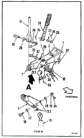
INSTALL YAW IDLER BELLCRANK
(Continued)
11-94
6.
Position link (19) in bellcrank (7). Install bolt (18),
two washers (17 and 16) and nut (15). Do not
torque nut at this time.
7.
Remove nut (20), two washers (21 and 22), and
bolt (23) from bellcrank (7).
7.1.
Remove slipfit bushing (21.1) from position spring
support adjustment strap (24). Clean bushing
with dry cleaning solvent (E162) and cleaning
cloth (E120). Wear gloves (E184.1) and goggles.
7.2.
Coat bushing (21.1) with epoxy primer (E292).
Install bushing in position spring support (24),
with shoulder against lug (25).
8.
Untie and position spring support adjustment
strap (24) marked hole on bellcrank (7), inboard
of lug (25). Install bolt (23), with head outboard,
two washers (22 and 21), and nut (20). Torque
nut to 15 to 25 inch-pounds. Install cotter pin
(26).
9.
Remove nut (27), two washers (28 and 29), and
bolt (30) from bellcrank (7).
10.
Untie and position spring (31) on bellcrank (7).
Install bolt (30), two washers (29 and 28), and
nut (27).
11.
Torque four nuts (1, 10, 15, and 27) to 30 to 45
inch-pounds. Install four cotter pins (32, 33,
34, and 35).
12.
Check five bolts (3, 13, 18, 23, and 30).
Bolts shall not rotate with torque less than 10
inch-pounds. There shall be no axial looseness,
if bolt rotates or is loose, add washer under nut,
and repeat step 8 or 11 as required.
INSPECT
FOLLOW-ON MAINTENANCE:
Remove servocylinder safety blocks (Task 11-29).
Perform operational check of flight control system
(TM 55-1520-240-T).
Install closet backup panel (Task 2-2).
Install closet acoustic blanket (Task 2-108).
END OF TASK
11-498