TM 55-1520-240-23-9
11-81
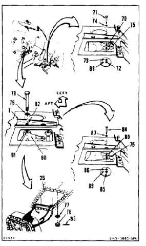
INSTALL PILOT’S COCKPIT CONTROL ASSEMBLY
(Continued)
11-81
INSTALL YAW CONNECTING LINK
45.
Move bellcrank (70) for access to bolt (71).
Remove nut (72), two washers (73 and 74) and
bolt (71).
FLIGHT SAFETY PARTS
This is an installation critical flight
safety part. All aspects of its assembly
and installation must be ensured.
Ensure that both rod end jam nuts are
installed and torqued.
Ensure that the rivet through the fixed
rod end bearing is secure.
At installation of this component,
ensure proper attaching hardware
(impedance type bolt, nut, and
washers) is installed including
verification of bolt head orientation,
torque, and installation of cotter pins.
Loose attachments within flight control
primary linkage will degrade aircraft
control. Missing components will
cause loss of control.
46.
Slide yaw connecting link (75) from left and
position in bellcrank (70).
47.
Install bolt (71), two washers (74 and 73), and
nut (72) in bellcrank (70).
48.
Working through left access (26) remove nut (76)
and washer (77) from bolt (78).
49.
Have helper working from cockpit, remove bolt
(78) and washer (79) from assembly (1).
50.
Move bellcrank (80) forward to align bellcrank
pivot hole (81) and hole (82).
51.
Install washer (79) and bolt (78) through
assembly (1) and bellcrank (80).
52.
Working through left access (26), install washer
(77) and nut (76).
53.
Torque nut (76) to 60 to 90 inch-pounds. Install
cotter pin (83).
54.
Have helper working from cockpit, move
bellcrank (80) for access to bolt (84). Remove
nut (85) two washers (86 and 87) and bolt (84).
55.
Position link (75) in bellcrank (80).
56.
Install bolt (84), two washers (87 and 86), and
nut (85) in bellcrank (80).
57.
Torque nuts (72 and 85) to 30 to 60 inch-pounds.
Install two cotter pins (88 and 89).
58.
Check bolts (71, 78, and 84). Bolts shall not
rotate with torque less than 10 inch-pounds.
There shall be no axial looseness. If bolt rotates
or is loose, add washer under nut and repeat
step 53 or 57.
11-425