TM 55-1520-240-23-9
11-81
INSTALL PILOT’S COCKPIT CONTROL ASSEMBLY
(Continued)
11-81
Do not install bolts unless bushings
are in bellcranks; otherwise, damage
to bellcranks will result.
NOTE
Impedance bolts are installed in flight
control connections. These bolts
are self-retaining and require special
torque and nut (Task 1-13).
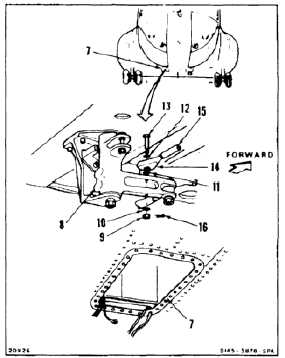
CONNECT CONTROL STICK INDICATOR
4.
Working through right access (7), move bellcrank
(8) fully forward.
5.
Remove nut (9), three washers (10, 11, and 12),
and bolt (13) from bellcrank (8).
6.
Position rod end (14) of indicator (15) on top of
bellcrank (8).
7.
Position washer (11) between rod end (14)
and bellcrank (8). Install washer (12) bolt (13),
washer (10), and nut (9). Torque nut to 30 to 60
inch-pounds. Install cotter pin (16).
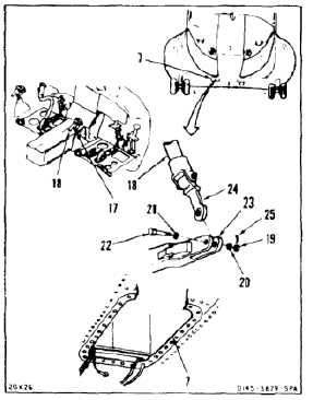
CONNECT THRUST CONTROL
8.
Remove strap (17) from thrust control (18). Set
control fully down.
9.
Working through right access (7), remove nut
(19), two washers (20 and 21), and bolt (22) from
bellcrank (23).
10.
Position link (24) in bellcrank (23).
11.
Install bolt (22), two washers (21 and 20), and
nut (19).
12.
Torque nut (19) to 30 to 60 inch-pounds. Install
cotter pin (25).
13.
Check bolt (22). Bolt shall not rotate with torque
less than 10 inch-pounds. There shall be no
axial looseness. If bolt rotates or is loose, add
washer under nut and repeat step 12.
11-421