TM 55-1520-240-23-7
9-160
ASSEMBLE WINCH CONTROL GRIP (AVIM)
(Continued)
9-160
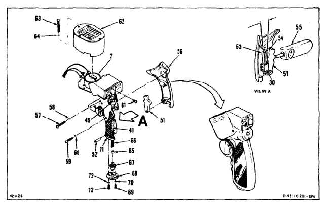
22.
Position trigger (51) in right handle (56). Install
pin (52).
23.
Adjust rear contact (53) gap to 0.060 inch
minimum to front contact (54).
24.
Using push-pull indicating scale (55) against the
trigger (51), apply a pressure of 6 to 8 ounces.
Switch (30) shall activate. If not within 6 to 8
ounce range, repeat step 23.
INSPECT
25.
Position right handle (56) to left handle (41).
Install screw (57), washer (58), screw (59), and
washer (60).
26.
Install screw (61) in plate (48).
27.
Position cover (62) on plate (2). Install three
screws (63) and washers (64).
28.
Install sleevings (E204) (65) on 12 wires (66).
29.
Remove tape and solder twelve wires (66) to
receptacle (67). Remove tags. Coat receptacle
connections with varnish (E435). Slide twelve
sleeves (65) over receptacle connections. Wear
gloves (E186).
30.
Position receptacle (67) to cover (68). Install four
screws (69) and washers (70).
31.
Position cover (68) in opening (71). Install four
screws (72) and washers (73).
INSPECT
FOLLOW-ON MAINTENANCE:
Test winch control grip (Task 9-161).
END OF TASK
9-642