TM 55-1520-240-23-6
7-153
INSTALL PRESSURE CONTROL MODULE
(Continued)
7-153
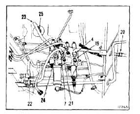
8.
Connect tube (4) to LH ENG START PRESS port
(19) and fitting (20). Remove tag.
9.
Connect tube (7) to RH ENG START PRESS port
(21) and fitting (22). Remove tag.
10.
Connect tube (23) to PRESS INL port (24) and
fitting (25). Remove tag.
11.
Deleted.
Electrical connectors are to be
tightened no more than 1/16 to
1/8 turn beyond finger-tight during
installation, otherwise they will be
damaged.
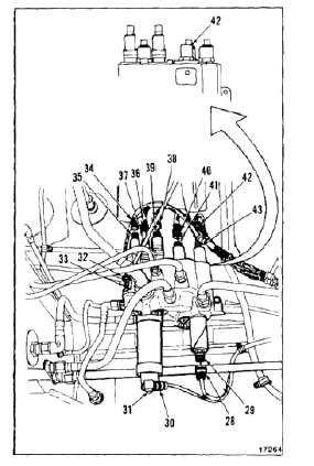
12.
Connect connector (28) PRESS XMTR to
transmitter (29). Remove tag.
13.
Connect connector (30) to filter indicator (31).
Remove tag.
14.
Connect connector (32) to PRESS SWITCH (33).
Remove tag.
15.
Connect connector (34) to RAMP PWR V (35).
Remove tag.
16.
Connect connector (36) to RH ENG PLT V (37).
Remove tag.
17.
Connect connector (38) to PTU PWR CV valve
(39). Remove tag.
18.
Connect connector (40) to WHLBK PWR V valve
(41). Remove tag.
19.
Check PTU PWR V valve (43) if part number is
145HS204-3. Connect connector (42) to valve
(43). Remove tag. If part number is 145HS204-1,
do not connect connector.
INSPECT
FOLLOW-ON MAINTENANCE:
Bleed utility hydraulic system (Task 7-336).
Perform operational check (TM 55-1520-240-T).
Close cargo ramp (TM 55-1520-240-T).
END OF TASK
7-675