TM 55-1520-240-23-6
7-86
INSTALL EXTENSIBLE LINK
(Continued)
7-86
4.
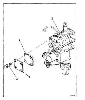
On removed extensible link (5), install shipping
cover (2) as follows:
NOTE
Make sure dash number on data plate
(8) is -8 or -12.
a.
Position shipping cover (2) and data plate
(8) on link (5).
b.
Install four screws (3).
c.
Lockwire screws (3). Use lockwire (E231).
5.
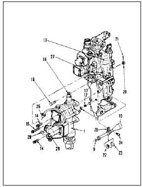
Install packing (9) on tube (10).
6.
Install two packings (11) on transfer tube (12).
6.1.
Install transfer tube (12) in extensible link (1).
Lockwire tube to link. Use lockwire (E231).
7.
Position extensible link (1) on actuator (13).
8.
Install two screws (14) and screw (15) in
assembly (1).
9.
Torque two screws (14) and screw (15) to 45
inch-pounds.
10.
Lockwire screws (14 and 15). Use lockwire
(E231).
11.
Position rod (16) in link (17). Install bolt (18) and
nut (20).
12.
Torque nut (20) to 35 to 65 inch-pounds.
13.
Install cotter pin (21).
14.
Install tube (10) in extensible link.
15.
Install grommet (22) and tie-rap (23) on tube (10).
16.
Install screw (24) in clip (25) and actuator (13).
17.
Connect cable plug (26) to receptacle (27).
18.
Identify strap (28) with correct axis and install on
receptacle (29). (See Table A.)
INSPECT
FOLLOW-ON MAINTENANCE:
Perform ILCA test (Task 7-98).
END OF TASK
7-353


