TM 55-1520-240-23-5
6-4
REMOVE NO. 7 DRIVE SHAFT
(Continued)
6-4
NOTE
All shafts must be rotated as a unit to
keep blades in phase.
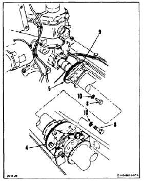
3.
Rotate shaft (9) to position two bolt holes in
adapter assemblies (4 and 5) at top of shaft.
4.
Support shaft (9) with cloths (E120) or barrier
material (E80).
5.
Remove three bolts (8) and washers (10) from
each end of shaft (9).
6.
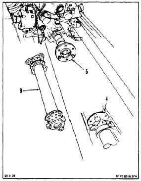
With aid of helper lift shaft (9) from between
adapter assemblies (4 and 5). Remove shaft.
FOLLOW-ON MAINTENANCE:
None
END OF TASK
6-20