TM 55-1520-240-23-4
5-112
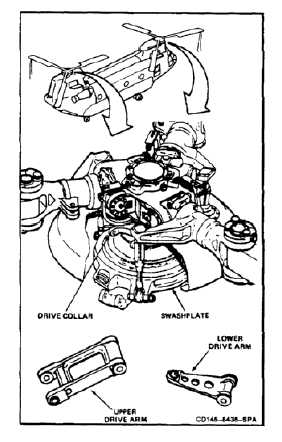
INSTALL DRIVE ARMS
5-112
INITIAL SETUP
Applicable Configurations:
All
Tools:
Aircraft Mechanic’s Tool Kit, NSN 5180-00-323-4692
Torque Wrench, 30 to 150 Inch-Pounds
Torque Wrench, 100 to 750 Inch-Pounds
Torque Wrench, 700 to 1600 Inch-Pounds
Torque Wrench, 100 to 500 Foot-Pounds
Depth Gage, Dial Indicating, 0 to 0.125 Inch
Materials:
Lockwire (E231)
Antiseize Compound (E75)
Gloves (E184.1)
Parts:
Cotter Pins
Personnel Required:
Medium Helicopter Repairer
Inspector
References:
Task 1-14
TM 55-1520-240-23P
General Safety Instructions:
Antiseize compound (E75) can irritate
skin and cause burns. Avoid contact
with skin, eyes, or clothing. In case
of contact, immediately flush skin
or eyes with water for at least 15
minutes. Get medical attention for
eyes.
NOTE
The procedure to install forward or aft
drive arms is similar. Differences are
noted in the text.
With 46 positive retention bolt is
installed at each end of the upper
drive arm. They have a pawl which
prevents nut or bolt removal unless
the pawl is depressed (Task 1-14).
Without 46 impedance bolts are
installed in upper and lower drive arm
lugs. These bolts are self-retaining
and require a special nut and torque
(Task 1-14).
5-635