TM 55-1520-240-23-4
5-112
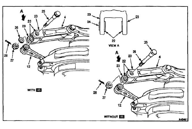
INSTALL DRIVE ARMS
(Continued)
5-112
16.
Check that shouldered bushing (22) is in place
in each upper drive arm lug (23). Check that a
shouldered bushing is in place at each side of
lower drive arm (12).
17.
Remove the retaining strap from shouldered
bushing (24). Position lower drive arm (12)
between upper drive arm lugs (23).
CONNECT UPPER AND LOWER DRIVE ARMS WITH
46
Do not lubricate thread of bolt.
18.
Apply a light coat of antiseize compound (E75) to
the shank and bushing of bolt (25). Wear gloves
(E184.1).
19.
Check that bushing (24) is in place. Install bolt
(25), washer (26), and nut (27). Torque the nut
to 480 inch-pounds. Continue tightening the
nut as needed to align cotter pin holes in the
nut and bolt. Do not exceed 900 inch-pounds.
Install cotter pin (28). Check that there is a gap
between the flange of bushing (24) and the
surface of lug (23).
CONNECT UPPER AND LOWER DRIVE ARMS
WITHOUT 46
Do not lubricate thread of bolt.
20.
Apply a light coat of antiseize compound (E75) to
the shank of bolt (25). Wear gloves (E184.1).
21.
Check that bushing (24) is in place. Install bolt
(25). Check that retaining ring (26) on the bolt is
clear of shouldered bushing (24) and is free to
turn.
22.
Install nut (27). Torque the nut to 500
inch-pounds. Continue tightening the nut as
needed to align cotter pin holes in the nut and
bolt (25). Do not exceed 700 inch-pounds.
23.
Install cotter pin (28).
24.
Apply torque of 165 inch-pounds to the head of
bolt (25). The bolt shall not turn.
5-638