TM 55-1520-240-23-4
5-93
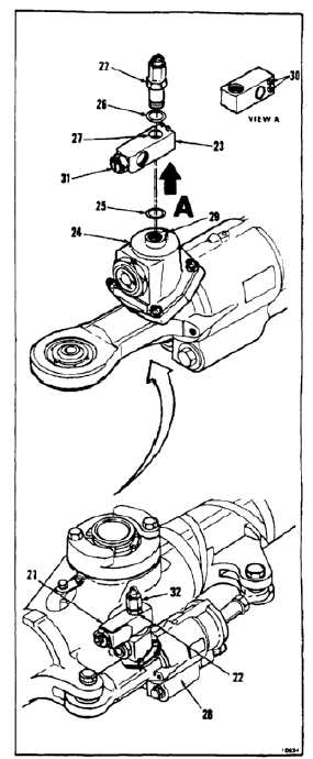
INSTALL SHOCK ABSORBER
(Continued)
5-93
11.
If required, position vent valve (21) for forward or
aft installation as follows:
NOTE
On forward head, vent valve marking
THIS SIDE UP FWD must face up.
On aft head, vent valve marking THIS
SIDE UP AFT must face up.
a.
Remove lockwire. Remove bolt fitting (22)
and valve body (23). Allow body to lift from
tank (24) and turn with filling.
b.
Remove packing (25). Remove fitting (22)
and packing (26).
c.
Coat fitting (22), hole (27), and packings (25
and 26). Use hydraulic fluid (E197).
Do not install packings in wrong
places. Packing at head of fitting
is thicker and smaller in diameter
than packing under body. Leakage
can occur if packings are installed in
wrong places.
d.
Install packing (26) on fitting (22).
e.
Position body (23) with markings up for head
where shock absorber (28) is installed.
f.
Install fitting (22) in body (23). Seat packing.
g.
Install packing (25) on fitting (22).
h.
Screw fitting (22) and body (23) halfway into
tank (24). Let body turn.
i.
Position body (23) so index lug (29) on tank
(24) is between lugs (30). Screw (31) will
face inboard. Hold body. Screw fitting (22)
all the way into tank.
j.
Lockwire cap (32) and fitting (22) to lugs (33).
Use lockwire (E231).
5-563


