TM 55-1520-240-23-4
5-93
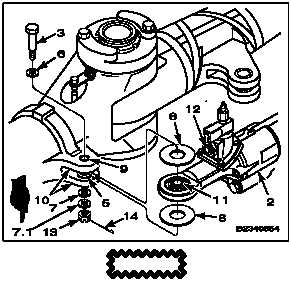
INSTALL SHOCK ABSORBER (Continued)
5-93
CONNECT SHOCK ABSORBER AT INBOARD LUGS
(WITHOUT 50 AND WITH 58 )
WARNING
Make sure blade is supported by sling
during installation; otherwise, damage
to helicopter or injury to personnel
could result.
CAUTION
Do not mix elastomeric bearings
with Teflon bearings on inboard end
of shock absorbers (With 45 ). If
elastomeric bearings are installed
in inboard end of shock absorber,
bushings 114H6803-2 must be
installed in shock absorbers.
NOTE
Aircraft/rotor heads (With 58 )
installed or "SK" behind the part
number can have either elastomeric
or Teflon bearing shock absorber/lag
dampers installed. Bolt (3) can either
be part number BACB30ST1239, or
145R3119-3, or bolt 145R3650-4 with
the bushing removed from the bolt.
5.
Install shock absorber (2) with bearing (11) and
two Teflon washers (8) between inboard lugs
(10). Face sight indicator (12) up and inboard.
6.
Install countersunk washer (6) on bolt (3), with
countersink toward bolthead.
6.1.
Before torquing bolts for shock absorbers (With
45 ) position the blade over the tunnel cover and
install the lead lag tool (T72). This removes the
load of the blade and prevents uneven torquing
with elastomeric bearings.
CAUTION
Positive retention bolts are installed in
shock absorber bearings. These bolts
require special torque (Task 1-14).
Do not torque bolt until a qualified
inspector has verified that sliding
bushing (5) is installed.
Antiseize compound on thread of bolt
or nut may result in over-torquing.
(With 45 ) Uneven torquing of
elastomeric bearings could cause the
bearing to become unseated during
flight.
7.
Align holes in lugs (10) and bearing (11). Install
bolt (3) and washer (7).
7.1.
Check that there is no antiseize compound on
thread of nut (13). Install nut on bolt (3). Torque
nut to 110-250 foot-pounds. Install cotter pin
(14). Washer (7) may be added to align cotter
pin.
NOTE
Use AN960-1216 and/or
AN960-1216L washers (7.1) between
nut (13) and MS20002-12 washer (7)
as required to align cotter pin hole in
bolt (3) with slot in nut (13).
7.2.
Check that Teflon washers (8) are not caught
between bearing (11) and bushings (5 or 9).
After torque application, the Teflon washers must
be free to turn.
5-560
Change 2