TM 55-1520-240-23-4
5-92
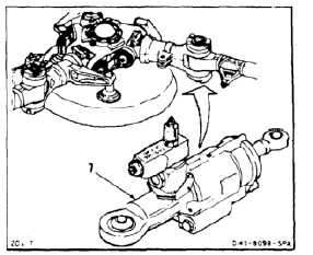
PLACE SHOCK ABSORBER IN SERVICE
(Continued)
5-92
4.
Install shock absorber (7) (Task 5-93).
5.
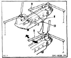
Bleed air from shock absorber as follows:
a.
Remove ties (8) from blade (9) to landing
gear shackles (10).
NOTE
Blade is used as lever to move shock
absorber.
b.
Have helpers lift and move blade (9). Move to
full lead and full lag positions. Repeat cycle
five times. Have helpers lower blade.
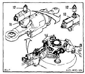
c.
Check that fluid level is within center of sight
indicator (11). If fluid is within center, go to
Follow-On Maintenance.
d.
If fluid is not visible in center of indicator (11),
remove lockwire and cap (12).
e.
Add hydraulic fluid (E197) to tank (13) until
level is at center of indicator (11). Install cap
(12). Lockwire cap. Use lockwire (E231).
5-555