TM 55-1520-240-23-10
16-59.14 AN/ALE-47 PAYLOAD MODULE LOADING (Continued)
16-59.14
9.
Insert one impulse cartridge (7) into each flare
cartridge (5) in the payload module assembly (2).
NOTE
Refer to table below to determine
position of encoder pins in retaining
plate.
"X" = Coding Pin Installed
"O" = Coding Pin Not Installed
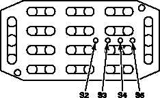
10.
Insert encoder pin screws (10) into appropriate
holes (S2, S3, S4, S5) from payload module side
of retaining plate.
ENCODER PIN
LOCATION
DISP.
NO.
AIRCRAFT
LOCATION
MAG
ID
S2
S3
S4
S5
1
LH LOWER
1
X
O
O
O
2
RH LOWER
8
O
O
O
X
3
LH UPPER
1
X
O
O
O
4
RH UPPER
8
O
O
O
X
11.
Install encoder pins (9) onto encoder pin screws
(10); tighten screws.
12.
Align retaining plate (3) over payload module (2).
CAUTION
Over-tighening retaining plate screws
may cause retaining plate to warp
resulting in erroneous flare counts or
misfires.
13.
While maintaining even hand pressure on
retaining plate (3) to prevent warping or buckling,
secure retaining plate with two screws (1).
FOLLOW-ON MAINTENANCE:
Install AN/ALE-47 payload modules per Task
16-59.13.
END OF TASK
Change 1
16-250.29