TM 55-1520-240-23-9
11-280
AFCS INTERFACE TEST
(Continued)
11-280
TEST 18
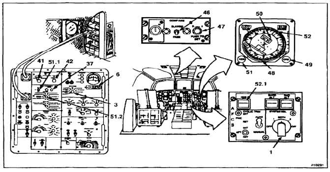
HORIZONTAL SITUATION INDICATOR NULL TEST
(BOTH)
117.
Set AFCS SYSTEM SEL switch (1) to 1 or 2.
(System under test.)
118.
Set METER SOURCE switch (3) to GYRO TEST.
119.
Set GYRO TEST SIGNAL MONITOR switch (41)
to HDG ERR.
120.
Set GYRO TEST SIGNAL MONITOR switch (42)
to SEL 1 or SEL 2.
120.1. SIGNAL SELECT switch should be position to
HDG ENGAGE ON.
121.
Set COMPASS switch (46) to SLAVED.
122.
Push and rotate PUSH TO SET switch (47) and
set compass card (48) to 0º.
123.
Rotate CR6 switch (49) set pointer (50) to 0º.
124.
Rotate HDG switch (51) and set bug (52) to 0º.
124.1. Set DISCRETE SIGNAL MONITOR switch (51.1)
to SEL 1 ON.
124.2. Set SIGNAL SEL 1 switch (51.2) to HDG
ENGAGED ON.
125.
Press HDG ENGAGED switch (52.1). STATUS A
light (37) shall come on. Read digital display (6).
Reading shall be -0.2 to +0.2 VAC.
NOTE
Depending on helicopters present
heading, compass card may drift.
Make sure voltage is read at 0º on
HSI.
END HORIZONTAL SITUATION NULL TEST (BOTH)
11-1191