TM 55-1520-240-23-9
11-280
AFCS INTERFACE TEST
(Continued)
11-280
TEST 16
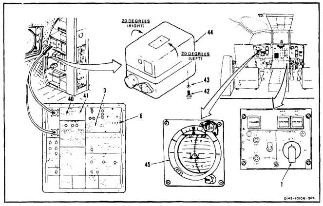
VERTICAL GYRO ROLL ATTITUDE TEST (BOTH)
98.
Set AFCS SYSTEM SEL switch (1) to 1 or 2.
(System under test.)
99.
Set METER SOURCE switch (3) to GYRO TEST.
100.
Set GYRO TEST SIGNAL MONITOR switch (40)
to ROLL.
101.
Set GYRO TEST SIGNAL MONITOR switch (41)
to XY. Read digital display (6). Reading shall be
-0.2 to +0.2 VAC.
102.
Set GYRO TEST SIGNAL MONITOR switch (41)
to YZ. Read digital display (6). Reading shall
be +9.0 to +11.0 VAC.
103.
Set GYRO TEST SIGNAL MONITOR switch (41)
to 2X. Read digital display (6). Reading shall be
-9.0 to -11.0 VAC.
104.
Set GYRO TEST SIGNAL MONITOR switch (41)
to XY.
105.
Remove three mounting screws (42), and
washers (43) from gyro (44).
106.
Have helper observe indicator (45). Tilt gyro
(44) about 20º left roll. Read digital display (6).
Reading shall be -3.0 to -5.0 VAC.
107.
Have helper observe indicator (45). Tilt gyro
(44) about 20º right roll. Read digital display (6).
Reading shall be +3.0 to +5.0 VAC.
108.
Install three screws (42) and washers (43) in
gyro (44).
END VERTICAL GYRO ROLL ATTITUDE TEST
(BOTH)
11-1189