TM 55-1520-240-23-3
4-140
INSTALL AND RIG POWER TURBINE CONTROL LINKAGE
(Continued)
4-140
2.
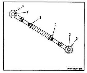
Measure distance between centers of holes (3)
in rod end bearings (4 and 5). If length is same
as dimension A found in step 1, go to step 3. If
not, do the following:
a.
Remove lockwire and loosen two nuts (6 and
7).
b.
Rotate two bearings (4 and 5) alternately
until distance between centers of holes (3) is
same as dimension A.
c.
Make sure bearings (4 and 5) are aligned.
d.
Tighten nuts (6 and 7). Do not lockwire nuts
at this time.
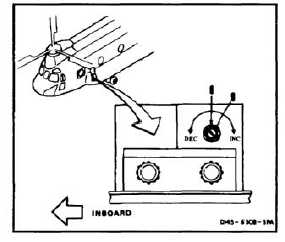
Do not force resistor at either limit of
its range. Internal damage to resistor
can result.
NOTE
Nominal distance between centers
of holes in rod end bearings is 10.55
inches.
3.
Loosen nut (8). Set variable resistor shaft
(9) to halfway between full clockwise and
counterclockwise positions.
3.1.
Connect the battery (Task 1-39), turn on the
electrical power, and the hydraulic power.
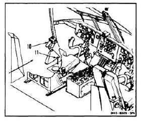
4.
Set thrust control (10) to neutral. Install rigging
pin (T122) (11).
4-455