TM 55-1520-240-23-3
4-140
INSTALL AND RIG POWER TURBINE CONTROL LINKAGE
4-140
INITIAL SETUP
Applicable Configurations:
Without 74
Tools:
Powerplant Repairer’s Tool Kit, NSN
5180-00-323-4944
Torque Wrench, 30 to 150 Inch-Pounds
Thrust Control Rigging Pin (T122)
Stopwatch
Materials:
Lockwire (E229)
Parts:
Cotter Pins
Personnel Required:
Aircraft Powerplant Repairer (2)
Inspector
References:
TM 55-1520-240-23P
Equipment Condition:
Battery Disconnected (Task 1-39)
Hydraulic Power Off
Electrical Power Off
Forward Floor Panels Removed (Task 2-81)
Electrical Compartment Access Door Open (Task 2-2)
Adjust Engine Droop Eliminator Variable Resistors
(Task 4-118)
Replace Power Turbine RPM Limiting Stop (Task
4-137)
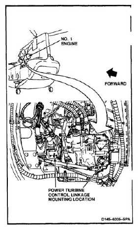
NOTE
Procedure is same to install and rig
power turbine control linkage on No.
1 or No. 2 engine. Installation and
rigging for No. 1 engine is shown here.
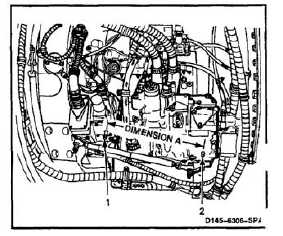
1.
Measure dimension A from actuator shaft (1) to
fuel control shaft (2).
4-454