TM 55-1520-240-23-3
3-56
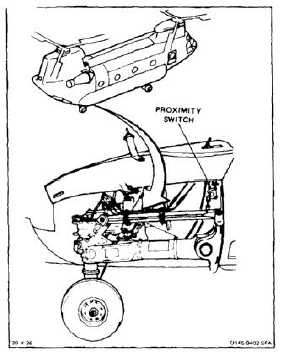
ADJUST AFT LANDING GEAR PROXIMITY SWITCH
3-56
INITIAL SETUP
Applicable Configurations:
All
Tools:
Aircraft Mechanic’s Tool Kit, NSN 5180-00-323-4692
Materials:
Lockwire (E231)
Personnel Required:
Medium Helicopter Repairer
Avionics Mechanic
Inspector
References:
Task 1-24
Equipment Condition:
Battery Disconnected (Task 1-39)
Electrical Power Off
Hydraulic Power Off
Aft Landing Gear Access Panels Open (Task 2-2)
NOTE
Procedure is same for left or right
proximity switch. Right switch is
shown here.
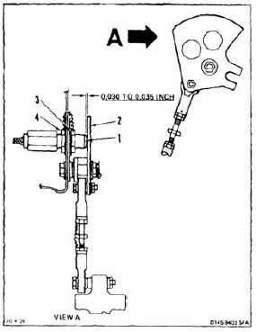
1.
Measure gap between face of switch (1) and
target (2). Use thickness gage.
a.
If gap is less than .030 inch or greater than
.035 inch, go to step 2.
b.
If gap is not less than .0300 inch and not
greater than .035 inch, go to step 6.
2.
Remove lockwire from nuts (3 and 4).
3.
Loosen nuts (3 and 4). Adjust gap to correct
dimension.
4.
Tighten nuts (3 and 4). Check gap is within
correct limits.
INSPECT
5.
Install lockwire (E231) between nuts (3 and 4).
3-146