TM 55-1520-240-23-3
3-55
INSTALL AFT LANDING GEAR PROXIMITY SWITCHES, TARGET, AND ADJUSTER
LINK
(Continued)
3-55
6.
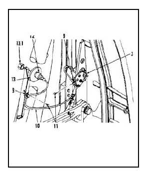
Position two cable clamps (9) on cable (10) of
proximity switch (3).
7.
Attach clamps (9) to structure with two screws
(11).
8.
Connect connector (12) to receptacle (13).
Lockwire receptacle retaining nut (13.1). Use
lockwire (E231).
INSPECT
INSTALL TARGET
9.
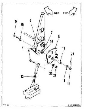
Install bolt (14), head inboard, and washer (15)
through bracket (4).
10.
Install washer (16), bushing (17), target (8),
washer (18), and nut (19) on bolt (14).
11.
Torque nut (19) to 25 to 35 inch-pounds. Install
cotter pin (20).
INSPECT
12.
Rotate target (8) past face (7) of switch (3).
Measure gap between switch face and target. If
gap is not .030 to .035 inch, adjust switch (Task
3-56).
13.
Install bolt (21) through adjuster link (22) and
target (8). Install washer (23) and nut (24).
INSPECT
3-144


