TM 55-1520-240-23-9
11-9
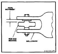
INSPECT BELLCRANK AND CONNECTING LINK BEARINGS (INSTALLED)
11-9
INITIAL SETUP
Applicable Configurations:
All
Tools:
As Required
Materials:
Wire (E233)
Insulation Sleeving (E204)
Personnel Required:
Medium Helicopter Repairer
Inspector
References:
TM 1-1500-204-23
TM 55-1500-322-24
Task 11-8
Equipment Condition:
Battery Disconnected (Task 1-39)
Electrical Power Off
Hydraulic Power Off
Servocylinder Safety Blocks (T31) Installed (Task
11-28)
Servocylinder Connecting Links Disconnected (Task
11-192)
Access Door Open (As Required) (Task 2-2)
ANTIFRICTION TYPE BEARINGS
1.
Check antifriction type rod end bearing as
follows:
a.
Stop bellcrank from moving. Use wire (E233)
covered with vinyl tubing (E204) or wood
blocks.
b.
Pull then push bearing radially. If looseness
is more than 0.004 inch, remove link and
perform Task 11-8.
NOTE
Rolling element bearings are located
in the flight control closet area, 1st
and 2nd stage mixing units, forward
pylon, tunnel area, aft fuselage, aft
pylon and pedal box area only.
c.
Where there is evidence of an unserviceable
bearing, disconnect sufficient parts of the
system as required so that the individual
bearings may be examined by hand rotation.
Serviceable condition, well-lubricated
bearings feel smooth with no perceptible
roughness, catching or binding. No excessive
external corrosion or worn plating should
be evident on the bearing exterior, and
shields and seals should be undamaged and
operable.
11-42