TM 55-1520-240-23-9
11-96
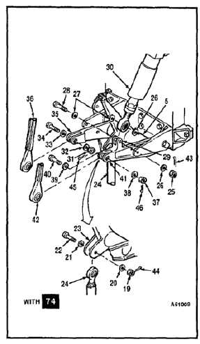
INSTALL PALLET THRUST IDLER BELLCRANK
(Continued)
11-96
j.
Remove nut (19), two washers (20 and 21),
and bolt (22) from lugs (23) of bellcrank (5).
k.
Position input connecting link (24) between
lugs (23) of bellcrank (5). Install bolt (22),
two washers (21 and 20), and nut (19). Do
not torque nut at this time. Remove tag from
link (24).
l.
Remove nut (25), four washers (26 and 27),
and bolt (28) from lugs (29) of bellcrank (5).
m.
Position thrust CPT (30) between lugs (29) of
bellcrank (5). Install bolt (28), four washers
(27 and 26), and nut (25). Do not torque nut
at this time. Remove tag from CPT (30).
n.
Remove nut (31), two washers (32 and 33),
and bolt (34) from lugs (35) of bellcrank (5).
o.
Position damper connecting link (36) between
lugs (35) of bellcrank (5). Install bolt (34),
two washers (33 and 32), and nut (31). Do
not torque nut at this time. Remove tag from
link (36).
p.
Remove nut (37), two washers (38 and 39),
and bolt (40) from lugs (41) of bellcrank (5).
q.
Position CCDA connecting link (42) between
lugs (41) of bellcrank (5). Install bolt (40),
two washers (39 and 38), and nut (37). Do
not torque nut at this time. Remove tag from
link (42).
r.
Torque nut (25) to 15 to 20 inch-pounds.
Install cotter pin (43).
s.
Torque three nuts (19, 31, and 37) to 30 to
45 inch-pounds. Install three cotter pins (44,
45, and 46).
t.
Check four bolts (22, 28, 34, and 40). Bolts
shall not rotate with torque less than 10
inch-pounds. There shall be no axial
looseness. If bolt rotates or is loose, add
washer under nut, and repeat step r or s.
INSPECT
FOLLOW-ON MAINTENANCE:
Rig pallet thrust idler bellcrank (Task 11-48).
Remove servocylinder safety blocks (Task 11-29).
Adjust thrust detent (Task 11-109).
Perform operational check of flight control system
(TM 55-1520-240-T).
Install closet backup panel (Task 2-2).
Install closet acoustic blanket (Task 2-108).
END OF TASK
11-508