TM 55-1520-240-23-9
11-60
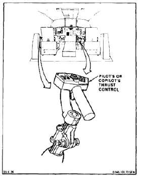
INSPECT THRUST CONTROL
11-60
INITIAL SETUP
Applicable Configurations:
All
Tools:
Aircraft Mechanic’s Tool Kit, NSN 5180-00-323-4692
Materials:
None
Personnel Required:
Medium Helicopter Repairer
Inspector
Equipment Condition:
Battery Connected (Task 1-39)
Electrical Power On
Hydraulic Power On
1.
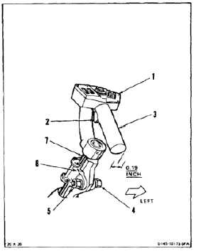
Inspect thrust control (1) for looseness as follows:
a.
Press THRUST CONT BRAKE TRIGGER
switch (2). Pull control (1) up about 3 inches.
Release switch.
b.
Push control grip (3) left then right. Apply
force of about 10 pounds at end of grip.
c.
Measure movement at end of grip (3).
Distance must not be more than 0.19 inch. If
distance is less, go to step f. If more, perform
steps d and e then go to step f.
d.
Check looseness at pivot block bolt (4). If
loose, tighten nut (5).
e.
Check looseness between shaft (7) and ball
spline assembly (8). If looseness causes
0.19 inch movement at grip (3) replace ball
spline assembly.
f.
Press switch (2). Position control (1) fully
down. Release switch.
INSPECT
FOLLOW-ON MAINTENANCE:
Remove hydraulic power.
Remove electrical power.
END OF TASK
11-278