TM 55-1520-240-23-9
11-55
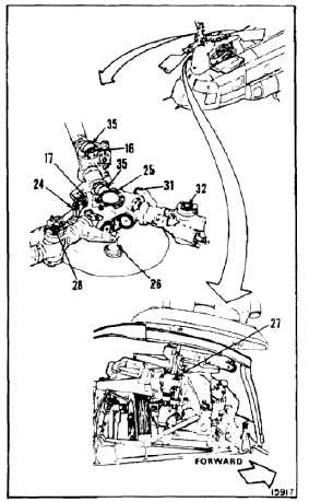
RIG FORWARD ROTARY WING BLADES
(Continued)
11-55
Keep movement on aircraft
to minimum; otherwise, false
measurements can occur.
19.
Work from forward right work platform, position
protractor (35) on rotor hub (25) above and
parallel to horizontal pin (17). Measure and
record angle of hub. Remove protractor.
Do not rotate protractor between
measurements; otherwise, false
measurements will occur.
20.
Position protractor (35) on vertical pin (16)
parallel to pin (17). Measure and record angle of
pin. Remove protractor.
21.
Check angles measured in steps 19 and 20.
Subtract angle of step 19 from angle of step 20.
Difference must be -3.4º to -3.7º. If not, adjust
pitch link (24) (Task 5-94), then repeat steps 19,
20, and 21.
22.
Turn rotor hub (25). Position pitch link (26) above
servocylinder (27).
23.
Repeat steps 19, 20, and 21 for vertical pin (28).
24.
Turn hub (25). Position pitch link (31) above
servocylinder (27).
25.
Repeat steps 19, 20, and 21 for vertical pin (32).
11-253