TM 55-1520-240-23-9
11-55
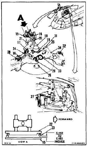
RIG FORWARD ROTARY WING BLADES
(Continued)
11-55
NOTE
Rigging tool (T129) or protractor can
be used to measure rotary wing blade
angles. Using tool (T129), perform
steps 4 thru 18. Using protractor,
perform steps 19 thru 26.
4.
Working from forward right work platform install
plate (15) in vertical pin (16), parallel to horizontal
pin (17).
5.
Install tool (T129) (18) in rotor shaft (19). Position
arm (20) parallel to pitch housing (21) with plate
(22) parallel and on plate (15).
6.
Measure gap between ball (23) and plate (15).
Gap must be 0.443 to 0.451 inches. If not, adjust
pitch link (24) (Task 5-94), then repeat step 6.
7.
Position tool (18) away from plate (15). Remove
plate from pin (16).
8.
Turn rotor hub (25) and position pitch link (26)
above forward right servocylinder (27).
9.
Install plate (15) in pin (28) parallel to horizontal
pin (29).
10.
Position arm (20) parallel to housing (30) with
plate (22) parallel and on plate (15).
11.
Repeat step 6 for pin (28) and link (26).
12.
Position tool (18) away from plate (15). Remove
plate from pin (28).
13.
Turn rotor hub (25) and position pitch link (31)
above forward right servocylinder (27).
14.
Install plate (15) in pin (32) parallel to pin (33).
15.
Position arm (20) parallel to housing (34) with
plate (22) parallel and on plate (15).
16.
Repeat step 6 for pin (32) and link (31).
17.
Remove tool (18) from shaft (19).
18.
Remove plate (15) from pin (32), then go to step
26.
11-252